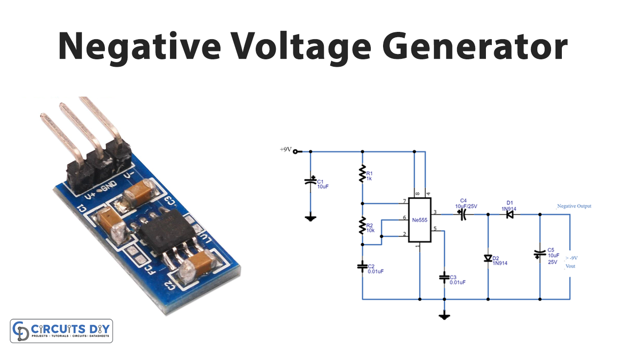
Smart Tips About How To Convert Negative Voltage Positive

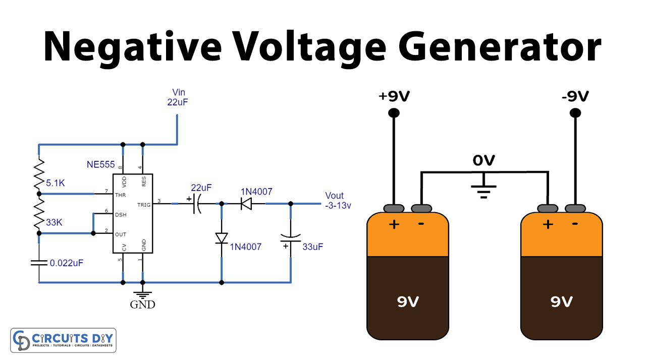
Generator Design Voltage At Malik Keck Blog
Navigating the Negative
1. Why Bother Converting Negative to Positive Voltage?
Ever wondered why you'd want to flip a voltage from negative to positive? It's not just about making things look brighter, although a positive outlook is always appreciated! The reality is, many electronic circuits and devices are designed to operate with positive voltages. Think of op-amps, microcontrollers, and a whole host of sensors. They need that positive push to do their job. If you're dealing with a circuit that naturally spits out a negative voltage — say, from a certain type of sensor or power supply configuration — you'll need a way to convert it before you can feed it into these positive-loving components. It's like translating between languages; you need to get the voltage into a format the receiving circuit understands.
So, where do negative voltages even come from? Well, some sensors inherently generate them based on physical phenomena. For example, certain pressure sensors or thermocouples can output small negative voltages. Also, in some power supply designs, particularly those using charge pumps or inverters, negative voltages are created as part of the process of generating different voltage levels. Understanding the origin of the negative voltage is key to choosing the best conversion method. Knowing the source helps in anticipating the characteristics of the voltage, like its magnitude, stability, and any potential noise.
Think of it like this: you have a glass of water that's ice-cold (negative voltage), but you need it at room temperature (positive voltage compatibility) to properly hydrate your circuit (the device you're powering). You wouldn't just throw the cold water at it; you'd need a way to gently warm it up (convert the voltage). The conversion method will depend on how cold the water is to start with!
Ultimately, converting negative voltage to positive allows you to integrate diverse components seamlessly into your electronic projects. It's about compatibility and ensuring that every part of your circuit plays nicely together, creating a harmonious and functional whole. Plus, it opens up a wider range of possibilities in your designs because you're not limited to only working with negative voltage components. It's a bit like getting the right adapter for your phone when you travel to a new country; essential for smooth operation.

Charge, Current, Voltage, Power, Energy Ppt Download
The Op-Amp Inverting Amplifier
2. How This Circuit Works Its Magic
One of the most common and reliable ways to convert negative voltage to positive is using an op-amp in an inverting amplifier configuration. Op-amps are incredibly versatile little chips, and this particular setup uses their properties to flip the sign of the voltage. The basic idea is that you feed the negative voltage into the op-amp's inverting input through a resistor. Then, you have another resistor connecting the output of the op-amp back to the inverting input. This creates a negative feedback loop, which is crucial for the circuit's stability and proper operation.
The magic of this circuit lies in its gain. The gain of the inverting amplifier is determined by the ratio of the two resistors: the feedback resistor (Rf) and the input resistor (Rin). Specifically, the gain is -Rf/Rin. Notice the negative sign? That's what does the trick! If you choose Rf and Rin to be equal, the gain becomes -1. This means the output voltage will be the exact opposite of the input voltage. So, if you feed in -5 volts, you'll get +5 volts out! If you need a different scaling, just adjust the resistor values accordingly.
The beauty of using an op-amp is its precision and stability. When properly configured, the output voltage will be a very accurate reflection of the input voltage, just with the opposite sign. This is especially important when you're dealing with sensitive circuits that require accurate voltage levels. Another advantage is that op-amps can provide a decent amount of current, which means you can drive other circuits with the converted voltage without significantly affecting its value. It's like having a voltage booster and sign flipper all in one handy package.
However, there are a few things to keep in mind. Op-amps require a power supply to operate. This means you'll need to provide both a positive and negative voltage to the op-amp itself. Also, op-amps have a limited bandwidth, which means they might not be suitable for converting very high-frequency signals. But for most DC and low-frequency applications, the inverting amplifier is a solid and reliable solution. Think of it as the Swiss Army knife of voltage conversion; versatile and always ready to lend a helping hand (or voltage!).

About Generating Positive And Negative Voltage From The Same Power
The Transistor Inverter
3. Back to Basics
If you're looking for a more basic and potentially more efficient way to convert negative voltage to positive, a transistor inverter circuit might be just the ticket. This method utilizes the switching properties of transistors to invert the voltage. It's a simpler approach compared to using an op-amp, often requiring fewer components, which can be advantageous in certain situations.
The basic transistor inverter circuit consists of a transistor (usually a BJT or a MOSFET), a resistor connected to the base (or gate) of the transistor, and a load resistor connected to the collector (or drain). The negative voltage is applied to the base (or gate) resistor. When the negative voltage is present, it turns the transistor OFF (or reduces its conductivity). This allows the voltage at the collector (or drain) to be pulled HIGH (positive) by the load resistor. When the negative voltage is removed, the transistor turns ON, pulling the voltage at the collector (or drain) LOW (close to zero). Effectively, the negative voltage acts as an "off" signal, resulting in a positive output.
One of the key benefits of this approach is its simplicity. Transistor inverters require fewer components than op-amp circuits, which can reduce the overall cost and complexity of your design. They also tend to be more power-efficient, especially when switching at low frequencies. This can be a significant advantage in battery-powered applications. Furthermore, transistor inverters can often handle higher voltages and currents than op-amps, making them suitable for driving more demanding loads.
However, there are some trade-offs. Transistor inverters are generally less precise than op-amp circuits. The output voltage might not be a perfectly scaled version of the input voltage, and the switching speed can be limited by the transistor's characteristics. Also, the output impedance of a transistor inverter is typically higher than that of an op-amp, which can make it more susceptible to loading effects. Despite these limitations, for many applications where simplicity and power efficiency are paramount, the transistor inverter offers a compelling alternative to op-amp based solutions. Its like choosing a manual transmission car; it might not be as smooth as an automatic, but its often more direct and efficient.

The Diode Clipper
4. Clipping Away the Negativity (Literally!)
Okay, let's talk about a method that's a bit more brute force. The diode clipper, also known as a half-wave rectifier, is a very simple circuit that can effectively remove the negative portion of a voltage signal. It's not exactly a voltage converter in the strictest sense, but it can be used to achieve a positive voltage from a negative one, albeit with some limitations. Think of it as surgically removing the negativity rather than transforming it.
The basic diode clipper circuit consists of a diode connected in series with a resistor. The negative voltage is applied to the circuit. When the voltage is positive (or zero), the diode is forward-biased and conducts, allowing the voltage to pass through. However, when the voltage becomes negative, the diode is reverse-biased and blocks the voltage. This effectively "clips" off the negative portion of the signal, leaving only the positive portion. The resistor is there to limit the current flowing through the diode.
The main advantage of the diode clipper is its simplicity. It requires only two components and is incredibly easy to implement. It's also very fast, capable of handling high-frequency signals. Furthermore, it doesn't require any external power supply, which can be a plus in certain situations. The clipping action happens almost instantaneously, dictated solely by the properties of the diode.
However, and this is a big however, the diode clipper completely eliminates the negative portion of the signal. It doesn't invert it or scale it; it simply throws it away. This means you lose information and potentially introduce distortion. Also, the output voltage will be significantly lower than the input voltage, as you're only using half of the signal. Therefore, the diode clipper should only be used in situations where you simply need to ensure that the voltage is always positive and where the loss of information and reduction in voltage are acceptable. Think of it as a last resort; useful in a pinch, but not ideal for precise or delicate applications. It's like using a sledgehammer to crack a nut; technically effective, but not exactly elegant.

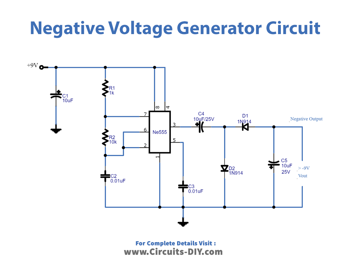
Negative Voltage Generator Circuit
Choosing the Right Method
5. Matching the Method to the Mission
So, you've got a negative voltage and need to make it positive. Great! But which method should you choose? The answer, as always, depends on the specifics of your application. Let's walk through some key considerations to help you make the right choice. First, consider the precision requirements. If you need a highly accurate and scaled version of the input voltage, the op-amp inverting amplifier is generally the best option. It offers excellent linearity and stability. If precision is less critical, the transistor inverter might suffice. For example, if you are just using the converted voltage to trigger a digital input, an exact voltage is likely unnessecary.
Next, think about the signal frequency. If you're dealing with a high-frequency signal, the diode clipper might be the only viable option. However, remember that it sacrifices information and voltage level. Op-amps have limited bandwidth, so they might not be suitable for very high frequencies. Transistor inverters can handle moderate frequencies, but their switching speed is limited by the transistor's characteristics. Therefore you must carefully consider the signal frequency to choose an appropriate method.
Power efficiency is another crucial factor. If you're working with a battery-powered device, you'll want to minimize power consumption. Transistor inverters tend to be more power-efficient than op-amp circuits, especially at low frequencies. Diode clippers don't require any external power, but they also waste half of the signal. Make sure to consider what your power limitations are before moving forward. This could save you energy and money in the long run.
Finally, consider the complexity and cost of the circuit. The diode clipper is the simplest and cheapest option, but it has significant limitations. Transistor inverters are also relatively simple and inexpensive. Op-amp circuits are more complex and require more components, but they offer superior performance. Ultimately, the best method is the one that meets your specific requirements while balancing performance, cost, and complexity. It's all about finding the right tool for the job and using it effectively. There is no "one size fits all" when it comes to voltage conversion, so ensure you carefully consider the trade-offs.

Frequently Asked Questions (FAQs) About Flipping Voltages
6. Your Burning Questions Answered!
Let's address some common questions that often pop up when dealing with negative-to-positive voltage conversion.
Q: Can I just connect the negative voltage backwards?
A: Oh, the temptation! While it might seem like a simple solution, directly reversing the polarity is generally a bad idea. Most circuits are designed to operate with specific voltage polarities, and applying a reversed voltage can damage them. It's like trying to put a puzzle piece in upside down; it just doesn't work and can cause problems. Always use a proper conversion method to ensure compatibility and prevent damage.
Q: What if I need to convert a very small negative voltage?
A: When dealing with small signals, amplification becomes crucial. An op-amp inverting amplifier is often the best choice, as it can provide both inversion and gain. You can adjust the resistor values to amplify the signal to a more usable level. Just make sure to consider the noise characteristics of the op-amp, as noise can be amplified along with the signal. Also, be aware that some op-amps are designed for small signal application.
Q: Are there integrated circuits (ICs) specifically designed for negative-to-positive voltage conversion?
A: Absolutely! Many ICs are designed for this purpose, often incorporating charge pumps or other techniques to generate a positive voltage from a negative input. These ICs can simplify the design process and offer improved performance compared to discrete solutions. A quick search on electronics vendor websites will turn up a variety of options!